RoofViews

Building Science

Parapets Part 3: An Example of Complexity

By Benjamin Meyer

March 23, 2020

Parapets on the side of a building

Part 1 of our discussion of parapets (Continuity of Control Layers) explored the many reasons continuity of water, air, thermal, and vapor control layers are necessary for long term performance.

In Part 2 of our discussion of parapets (Navigating Codes) discussed the challenges involved in navigating the range of national model codes and standards that will influence your design.

In Part 3, we're providing a practical example of applying the control layer continuity principles to construction trade sequencing while identifying some common challenges.

Control Layer Continuity

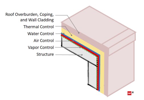
To better understand common parapet challenges, it is important to review continuity across the roof and wall systems, specifically the key four Control Layers: Water, Air, Thermal, and Vapor. These four key Control Layers should generally be continuous across all six sides of building enclosures. It is difficult–but not impossible–to achieve effective Control Layer continuity across building systems, especially at significant transitions like a parapet, where the roof system meets the wall system.

When beginning to think about designing enclosures, it's helpful to start with an ideal scenario. The configuration of the ideal wall system can be considered as follows: the cladding on the outside, continuous insulation keeping the rest of the control layers tempered in the middle, and structure to the inside. This "ideal" configuration can also be applied horizontally to the roof assembly. For an example of a transition, the roof and wall meet as an "ideal" flush edge with very simple transitions. As a system moves away from these ideal configurations, including parapets or other project constraints, transition details become more challenging and trade-offs have to be made.

"Ideal" Roof and Wall Transition

For more complex scenarios, like parapets, there are simple design tools to connect the control layers as they transition from the wall to the roof. The "pen test" — tracing each of the control layers across the building enclosure — is a helpful tool to design and communicate to the field the intent of the critical components and functions of the building enclosure.

Discussing control layers as they apply to a roof or wall alone is fairly manageable. But the process gets much more complicated when the roof meets the wall at the parapet condition (more here in Part 1 about Control Layers). The "pen test" is relatively easy in theory, but it can get complicated as we zoom in and consider the control layers at each condition, penetration, and transition.

Example of breaking down a parapet detail by the four control layers

In summary, the following are key points to maintain continuity of the control layers:

  • Water Control is managed by the roof membrane and the cladding. A secondary water control layer is often found against the structure, behind or below the exterior insulation.
  • Air Control can be managed at the deck level of the roof, which can more readily be married into the wall air barrier. The roof membrane can also be used as an air barrier as long as the detailing and transitions are done carefully.
  • Thermal Control continuity is maintained by connecting the roof and wall insulation, which can be challenging. It's important to be mindful of cavity insulation and the potential design risks of condensation at the thermal bridges.
  • Vapor Control can also be in the same plane as the air control layer, based on location needs, construction methodologies, and occupant use of the building.

Coordinating Complexity

This section provides a practical example of applying the control layer continuity principles to construction trade sequencing while identifying some common challenges. When confronted with a similar design as the example below, a general contractor may request alterations to the design in order to shorten the schedule or reduce costs. However, this value engineering process—the reduction of cost and time—may also comprise continuity of the control layers and reduce the intended long-term performance of the parapet systems (more about Value Engineering performance impacts). If unsure or designing high-performance buildings, engaging a building enclosure consultant can help anticipate continuity and constructability issues.

For the purposes of this discussion, the materials applied to the parapet assembly sequence (figures a – h below) are color-coded in their application step by their primary control layer function:

  • Water Control elements are shown in "blue"
  • Air Control elements are shown in "red"
  • Thermal Control elements are shown in "yellow"
  • Vapor Control elements are not shown separately (See the Vapor Control section above for applicability)

To help identify separate materials within a control layer, lighter and darker versions of the color are used to distinguish elements within the same step. Also dashed, or "hidden lines," are used to depict materials edges that may be overlapped or behind another layer in the sequence the same step.

(a) Initial condition

a. In the initial condition, the wall and roof deck are assembled up to their sheathing. The roof structure is a corrugated steel deck with a substrate board placed on top to provide a continuous surface for later air barrier adhesion. The exterior wall is steel framed with cavity insulation and exterior sheathing applied.

(b) Pre-treated corner

b: In preparation for the parapet wall construction, a strip of air barrier material is applied to the roof and wall edge with sufficient material for future integration with the remainder of the continuous air barrier. It is important to note the material on the wall side is not yet adhered to allow for future lapping to manage water in "shingle fashion" as required by the IBC. This can be accomplished by leaving a portion of the release liner in place for adhered materials.

(c) Parapet wall assembled

c: The parapet wall is then assembled on top of the roof deck in a platform framed configuration. If lateral bracing for the parapet is required, additional detailing and coordination would be needed.

(d) Air barrier integrated

d: After the parapet wall is in place, the remainder of the continuous air barrier can be applied to both the roof and wall systems. It is notable that if the air control layer is also intended to act as the WRB in the wall and parapet system (as shown in (d)), the application should start from the lowest point and work upward; this allows the subsequent layers to be lapped in shingle fashion. After the air barrier is applied to the walls (light red), the pre-applied strip of material can be lapped and secured over it (dark red in the center of the wall). The air barrier can then be applied to the roof deck (light red), up the backside and over the top of the parapet wall, and then terminate downward on the outside of the wall, lapping over in shingle fashion (dark red at the top of the wall). Lapped edges hidden behind the layers of air barrier materials are shown with dashed lines.

(e) Continuous insulation installed

e: The roof insulation and high-density coverboard can now be installed to the roof deck. These could be mechanically-fastened or adhered roof systems, but the use of mechanical-fasteners through the entire roof insulation can have a significant effect on the thermal performance of the building. Continuous insulation is also applied to the backside of the parapet wall to maintain continuity. The parapet blocking for the coping cap can now be installed. In this case, it also includes a layer of tapered insulation to provide slope back to the roof area and extend the continuous insulation to the top side of the parapet. Wood blocking is included as required to accomplish fastening to meet ANSI/SPRI ES-1 uplift requirements. After the parapet blocking is in place, a piece of counter flashing (shown in blue) is required to lap over the WRB prior to the installation of the walls continuous exterior insulation; flashing will later lap over the coping cap, but without this piece pre-installed, there would be a discontinuity in the water control layer. The bottom edge of the flashing, under the wall exterior insulation, is shown as a dashed line.

(f) Roofing and terminations installed

f: The roof membrane is applied to the roof area. An expansion joint may also be added at the joint between the roof and the parapet wall to allow for any expected movement between the systems. The membrane is then lapped and seams completed at the horizontal roof edge, extended up the backside of the parapet wall and terminated over the previously installed counter flashing on the face of the coping blocking. Terminating and lapping downward on the outside of the parapet wall maintains the continuity of the water control layer and provides a shingle-lap onto the secondary water control layer on the wall. The membrane over the coping blocking will also act as a secondary protection below the future coping cap. The coping cap attachment cleats and spline flashing are installed to the top edge of the parapet wall, bedding and treating the fasteners in sealant where they penetrate the membrane.

(g) Coping and cladding installed

g: The exterior cladding is then installed to the outside of the parapet and exterior walls (light blue). The coping cap is installed at the top of the wall, over the cleats and blocking (dark blue). The coping cap should be attached with the cleats as tested for by ASNI/SPRI ES-1, lapped over the cladding with drip edges on both sides, and maintain an overall slope towards the roof system to shed water.

Caption: (h) Final parapet assembly

h: The parapet assembly is now complete. During the service life of the building, regular inspections and maintenance are needed to retain the performance of the parapet. Recovering or replacement of the roof system in the future should utilize as-built documentation to understand how to continue to manage the wall and roof system control layers.

Enabling Success

Designing to maintain continuity of the four key control layers is important to ensure long-term performance. To get the design intent implemented in the field, detailing and identification of the control layer(s) in the drawings and specifications is critical. This can require the design to be pretty specific – more than just "or equal" or "by others". Specifying materials with known compatibility is important. And if the sequencing of components and members in the field impacts the intended continuity or performance of the control layer in the design – it should be addressed.

These challenges should be considered for every project. "Standard details" aren't able to capture project complexities such as high-to-low parapet transitions, terminations into a rising wall, and curtain wall flybys. These conditions all require unique detailing that must include continuous and well-conceived transitions. It's important to remember that control layer discontinuities can lead to failures in the field. For instance, air leakage can lead to concealed condensation, which can be mistaken for roof leaks.


For more information on parapet and control layer continuity, register for the Continuing Education Center webinar, Parapet Predicaments and Roof Edge Conundrums, sponsored by GAF and presented by Jennifer Keegan, AAIA and Benjamin Meyer, AIA, LEED AP.


For more information on parapet and control layer continuity, read the Continuing Education Center article, Parapets—Continuity of Control Layers, sponsored by GAF and written by Benjamin Meyer, AIA, LEED AP.


About the Author

Benjamin Meyer, AIA, LEED AP is a Roofing & Building Science Architect with GAF. Previous experience includes: enclosure consultant principal, technical management for enclosure products, commercial design, real estate development and construction management on a range of projects that included residential, educational, offices, and DuPont industrial projects. Industry positions include: Voting Member of the ASHRAE 90.1 Envelope and Project Committees, LEED Technical Committee member, past Technical Advisor of the LEED Materials (MR) TAG, and Director of the Air Barrier Association of America (ABAA).

Related Articles

An aerial shot of the student housing building on the Texas A&M campus.
Building Science

Are Hybrid Roof Assemblies Worth the Hype?

How can roofing assemblies contribute to a building's energy efficiency, resiliency, and sustainability goals? Intentional material selection will increase the robustness of the assembly including the ability to weather a storm, adequate insulation will assist in maintaining interior temperatures and help save energy, and more durable materials may last longer, resulting in less frequent replacements. Hybrid roof assemblies are the latest roofing trend aimed at contributing to these goals, but is all the hype worth it?What is a hybrid roof assembly?A hybrid roof assembly is where two roofing membranes, composed of different technologies, are used in one roof system. One such assembly is where the base layers consist of asphaltic modified bitumen, and the cap layer is a reflective single-ply membrane such as a fleece-back TPO or PVC. Each roof membrane is chosen for their strengths, and together, the system combines the best of both membranes. A hybrid system such as this has increased robustness, with effectively two plies or more of membrane.Asphaltic membranes, used as the first layer, provide redundancy and protection against punctures as it adds overall thickness to the system. Asphaltic systems, while having decades of successful roof installations, without a granular surface may be vulnerable to UV exposure, have minimal resistance to ponding water or certain chemical contaminants, and are generally darker in color options as compared to single ply surfacing colors choices. The addition of a single-ply white reflective membrane will offset these properties, including decreasing the roof surface temperatures and potentially reducing the building's heat island effect as they are commonly white or light in color. PVC and KEE membranes may also provide protection where exposure to chemicals is a concern and generally hold up well in ponding water conditions. The combination of an asphaltic base below a single-ply system increases overall system thickness and provides protection against punctures, which are primary concerns with single-ply applications.Pictured Above: EverGuard® TPO 60‑mil Fleece‑Back MembraneOlyBond 500™ AdhesiveRUBEROID® Mop Smooth MembraneMillennium Hurricane Force ® 1-Part Membrane AdhesiveDensDeck® Roof BoardMillennium Hurricane Force ® 1-Part Membrane AdhesiveEnergyGuard™ Polyiso InsulationMillennium Hurricane Force ® 1-Part Membrane AdhesiveConcrete DeckPictured Above: EverGuard® TPO 60‑mil Fleece‑Back MembraneGAF LRF Adhesive XF (Splatter)RUBEROID® HW Smooth MembraneDrill‑Tec™ Fasteners & PlatesDensDeck® Prime Gypsum BoardEnergyGuard™ Polyiso InsulationEnergyGuard™ Polyiso InsulationGAF SA Vapor Retarder XLMetal DeckWhere are hybrid roof assemblies typically utilized?Hybrid roof assemblies are a common choice for K-12 & higher education buildings, data centers, and hospitals due to their strong protection against leaks and multi-ply system redundancy. The redundancy of the two membrane layers provides a secondary protection against leaks if the single-ply membrane is breached. Additionally, the reflective single-ply membrane can result in lower rooftop temperatures. The addition of a reflective membrane over a dark-colored asphaltic membrane will greatly increase the Solar Reflectance Index (SRI) of the roof surface. SRI is an indicator of the ability of a surface to return solar energy into the atmosphere. In general, roof material surfaces with a higher SRI will be cooler than a surface with a lower SRI under the same solar energy exposure. A lower roof surface temperature can result in less heat being absorbed into the building interior during the summer months.Is a hybrid only for new construction?The advantage of a hybrid roof assembly is significant in recover scenarios where there is an existing-modified bitumen or built-up roof that is in overall fair condition and with little underlying moisture present. A single ply membrane can be installed on top of the existing roof system without an expensive and disruptive tear-off of the existing assembly. The addition of the single-ply membrane adds reflectivity to the existing darker colored membrane and increases the service life of the roof assembly due to the additional layer of UV protection. Additionally, the single-ply membrane can be installed with low VOC options that can have minimum odor and noise disturbance if construction is taking place while the building is occupied.Is the hybrid assembly hype worth it?Absolutely! The possibility to combine the best aspects of multiple roofing technologies makes a hybrid roof assembly worth the hype. It provides the best aspects of a single-ply membrane including a reflective surface for improved energy efficiency, and increased protection against chemical exposure and ponding water, while the asphaltic base increases overall system waterproofing redundancy, durability and protection. The ability to be used in both new construction and recover scenarios makes a multi-ply hybrid roof an assembly choice that is here to stay.Interested in learning more about designing school rooftops? Check out available design resources school roof design resources here. And as always, feel free to reach out to the Building & Roofing Science team with questions.This article was written by Kristin M. Westover, P.E., LEED AP O+M, Technical Manager, Specialty Installations, in partnership with Benjamin Runyan, Sr. Product Manager - Asphalt Systems.

By Authors Kristin Westover

December 28, 2023

Flat roof with hot air welded pvc membrane waterproofing for ballasted system
Building Science

Thermal Bridging Through Roof Fasteners: Why the Industry Should Take Note

What is going on here?No, this roof does not have measles, it has a problem with thermal bridging through the roof fasteners holding its components in place, and this problem is not one to be ignored.As building construction evolves, you'd think these tiny breaches through the insulating layers of the assembly, known as point thermal bridges, would matter less and less. But, as it happens, the reverse is true! The tighter and better-insulated a building, the bigger the difference all of the weak points, in its thermal enclosure, make. A range of codes and standards are beginning to address this problem, though it's important to note that there is often a time lag between development of codes and their widespread adoption.What Is the Industry Doing About It?Long in the business of supporting high-performance building enclosures, Phius (Passive House Institute US) provides a Fastener Correction Calculator along with a way to calculate the effect of linear thermal bridges (think shelf angles, lintels, and so on). By contrast, the 2021 International Energy Conservation Code also addresses thermal bridging, but only considers framing materials to be thermal bridges, and actually pointedly ignores the effects of point loads like fasteners in its definition of continuous insulation: "insulation material that is continuous across all structural members without thermal bridges other than fasteners and service openings" (Section C202). Likewise, The National Energy Code of Canada for Buildings: 2020 addresses thermal bridging of a number of building components, but also explicitly excludes fasteners: "in calculating the overall thermal transmittance of assemblies…fasteners need not be taken into account" (Section 3.1.1.7.3). Admittedly, point thermal bridges are often excluded because it is challenging to assess them with simple simulation tools.Despite this, researchers have had a hunch for decades that thermal bridging through the multitude of fasteners often used in roofs is in fact significant enough to warrant study. Investigators at the National Bureau of Standards, Oak Ridge National Laboratory, the National Research Council Canada, and consulting firms Morrison Hershfield and Simpson Gumpertz & Heger (SGH), have conducted laboratory and computer simulation studies to analyze the effects of point thermal bridges.Why Pay Attention Now?The problem has been made worse in recent years because changes in wind speeds, design wind pressures, and roof zones as dictated by ASCE 7-16 and 7-22 (see blogs by Jim Kirby and Kristin Westover for more insight), mean that fastener patterns are becoming denser in many cases. This means that there is more metal on average, per square foot of roof, than ever before. More metal means that more heat escapes the building in winter and enters the building in summer. By making our buildings more robust against wind uplift to meet updated standards, we are in effect making them less robust against the negative effects of hot and cold weather conditions.So, how bad is this problem, and what's a roof designer to do about it? A team of researchers at SGH, Virginia Tech, and GAF set out to determine the answer, first by simplifying the problem. Our plan was to develop computer simulations to accurately anticipate the thermal bridging effects of fasteners based on their characteristics and the characteristics of the roof assemblies in which they are used. In other words, we broke the problem down into parts, so we could know how each part affects the problem as a whole. We also wanted to carefully check the assumptions underlying our computer simulation and ensure that our results matched up with what we were finding in the lab. The full paper describing our work was delivered at the 2023 IIBEC Convention and Trade Show, but here are the high points, starting with how we set up the study.First, we began with a simple 4" polyisocyanurate board (ISO), and called it Case A-I.Next, we added a high-density polyisocyanurate cover board (HD ISO), and called that Case A-II.Third, we added galvanized steel deck to the 4" polyiso, and called that Case A-III.Finally, we created the whole sandwich: HD ISO and ISO over steel deck, which was Case A-IV.Note that we did not include a roof membrane, substrate board, air barrier, or vapor retarder in these assemblies, partly to keep it simple, and partly because these components don't typically add much insulation value to a roof assembly.The cases can be considered base cases, as they do not yet contain a fastener. We needed to simulate and physically test these, so we could understand the effect that fasteners have when added to them.We also ran a set of samples, B-I through B-IV, that corresponded with cases A-I through A-IV above, but had one #12 fastener, 6" long, in the center of the 2' x 2' assembly, with a 3" diameter insulation plate. These are depicted below. The fastener penetrated the ISO and steel deck, but not the HD ISO.One visualization of the computer simulation is shown here, for Case B-IV. The stripes of color, or isotherms, show the vulnerability of the assembly at the location of the fastener.What did we find? The results might surprise you.First, it's no surprise that the fastener reduced the R-value of the 2' x 2' sample of ISO alone by 4.2% in the physical sample, and 3.4% in the computer simulation (Case B-I compared to Case A-I).When the HD ISO was added (Cases II), R-value fell by 2.2% and 2.7% for the physical experiment and computer simulation, respectively, when the fastener was added. In other words, adding the fastener still caused a drop in R-value, but that drop was considerably less than when no cover board was used. This proved what we suspected, that the HD ISO had an important protective effect against the thermal bridging caused by the fastener.Next, we found that the steel deck made a big difference as well. In the physical experiment, the air contained in the flutes of the steel deck added to the R-value of the assembly, while the computer simulation did not account for this effect. That's an item that needs to be addressed in the next phase of research. Despite this anomaly, both approaches showed the same thing: steel deck acts like a radiator, exacerbating the effect of the fastener. In the assemblies with just ISO and steel deck (Cases III), adding a fastener resulted in an R-value drop of 11.0% for the physical experiment and 4.6% for the computer simulation compared to the assembly with no fastener.Finally, the assemblies with all the components (HD ISO, ISO and steel deck, a.k.a. Cases IV) showed again that the HD ISO insulated the fastener and reduced its negative impact on the R-value of the overall assembly. The physical experiment had a 6.1% drop (down from 11% with no cover board!) and the computer simulation a 4.2% drop (down from 4.6% with no cover board) in R-value when the fastener was added.What Does This Study Tell Us?The morals of the study just described are these:Roof fasteners have a measurable impact on the R-value of roof insulation.High-density polyisocyanurate cover boards go a long way toward minimizing the thermal impacts of roof fasteners.Steel deck, due to its high conductivity, acts as a radiator, amplifying the thermal bridging effect of fasteners.What Should We Do About It?As for figuring out what to do about it, this study and others first need to be extended to the real world, and that means making assumptions about parameters like the siting of the building, the roof fastener densities required, and the roof assembly type.Several groups have made this leap from looking at point thermal bridges to what they mean for a roof's overall performance. The following example was explored in a paper by Taylor, Willits, Hartwig and Kirby, presented at the RCI, Inc. Building Envelope Technology Symposium in 2018. In that paper, the authors extended computer simulation results from a 2015 paper by Olson, Saldanha, and Hsu to a set of actual roofing scenarios. They found that the installation method has a big impact on the in-service R-value of the roof.They assumed a 15,000-square-foot roof, fastener patterns and densities based on a wind uplift requirement of 120 pounds per square foot, and a design R-value of R-30. In this example, a traditional mechanically attached roof had an in-service R-value of only R-25, which is a 17% loss compared to the design R-value.An induction-welded roof was a slight improvement over the mechanically attached assembly, with an in-service value of only R-26.5 (a 12% loss compared to the design R-value).Adhering instead of fastening the top layer of polyiso resulted in an in-service R-value of R-28.7 (a 4% loss compared to the design R-value).Finally, in their study, an HD polyiso board was used as a mechanically fastened substrate board on top of the steel deck, allowing both layers of continuous polyiso insulation and the roof membrane to be adhered. Doing so resulted in an in-service R-value of R-29.5, representing only a 1.5% loss compared to the design R-value.To operationalize these findings in your own roofing design projects, consider the following approaches:Consider eliminating roof fasteners altogether, or burying them beneath one or more layers of insulation. Multiple studies have shown that placing fastener heads and plates beneath a cover board, or, better yet, beneath one or two layers of staggered insulation, such as GAF's EnergyGuard™ Polyiso Insulation, can dampen the thermal bridging effects of fasteners. Adhering all or some of the layers of a roof assembly minimizes unwanted thermal outcomes.Consider using an insulating cover board, such as GAF's EnergyGuard™ HD or EnergyGuard™ HD Plus Polyiso cover board. Installing an adhered cover board in general is good roofing practice for a host of reasons: they provide enhanced longevity and system performance by protecting roof membranes and insulation from hail damage; they allow for enhanced wind uplift and improved aesthetics; and they offer additional R-value and mitigate thermal bridging as shown in our recent study.Consider using an induction-welded system that minimizes the number of total roof fasteners by dictating an even spacing of insulation fasteners. The special plates of these fasteners are then welded to the underside of the roof membrane using an induction heat tool. This process eliminates the need for additional membrane fasteners.Consider beefing up the R-value of the roof insulation. If fasteners diminish the actual thermal performance of roof insulation, building owners are not getting the benefit of the design R-value. Extra insulation beyond the code minimum can be specified to make up the difference.Where Do We Go From Here?Some work remains to be done before we have a computer simulation that more closely aligns with physical experiments on identical assemblies. But, the two methods in our recent study aligned within a range of 0.8 to 6.7%, which indicates that we are making progress. With ever-better modeling methods, designers should soon be able to predict the impact of fasteners rather than ignoring it and hoping for the best.Once we, as a roofing industry, have these detailed computer simulation tools in place, we can include the findings from these tools in codes and standards. These can be used by those who don't have the time or resources to model roof assemblies using a lab or sophisticated modeling software. With easy-to-use resources quantifying thermal bridging through roof fasteners, roof designers will no longer be putting building owners at risk of wasting energy, or, even worse, of experiencing condensation problems due to under-insulated roof assemblies. Designers will have a much better picture of exactly what the building owner is getting when they specify a roof that includes fasteners, and which of the measures detailed above they might take into consideration to avoid any negative consequences.This research discussed in this blog was conducted with a grant from the RCI-IIBEC Foundation and was presented at IIBEC's 2023 Annual Trade Show and Convention in Houston on March 6. Contact IIBEC at https://iibec.org/ or GAF at BuildingScience@GAF.com for more information.

By Authors Elizabeth Grant

November 17, 2023

very severe hail
Building Science

Defending Against Very Severe Hail

Think that your roof doesn't need protection against hail? Think again.Severe hail events are increasing in geographic footprint and are no longer just in hail alley. The geographic region that experiences 1 inch or larger hailstones has expanded to be nearly two-thirds of the United States. Nearly 10 percent more U.S. properties, more than 6.8 million, were affected by hail in 2021 than in 2020. Coinciding with the increase in properties affected by a damaging hail event in 2021, there was also an increase in insurance claims, which rose to $16.5 billion from $14.2 billion in 2020.Figure 1: The estimated number of properties affected by one or more damaging hail events. Source: NOAA, graphed by VeriskAccording to data from Factory Mutual Insurance Company (FM Global), a leader in establishing best practices to protect buildings, the review of client losses between 2016-20, showed that the average wind/hail losses averaged $931,000 per event. That's a significant impact on a business, and it doesn't account for the other effects that a disruptive loss could have such as headaches from the process of repairing or replacing damaged roofs. As a result, designing the roof to withstand damage from hail events has become not only a best practice, but a necessity.Why does hail size matter?FM Approvals is a third-party testing and certification laboratory with a focus on testing products for property loss prevention using rigorous standards. FM Global, through the loss prevention data sheets, requires the use of FM Approved roof systems. FM Global estimates their clients lose about $130M each year on average from hail events in the United States. Given the increasing volume of severe hail events and the resulting property loss, damage, and financial impacts, FM Global added to the requirements in the FM Loss Prevention Data Sheet (LPDS) 1-34 Hail Damage in 2018. Loss Prevention Data Sheets provide FM's best advice for new construction and for Data Sheet 1-34, this includes new or reroofing projects on existing buildings. Data Sheet 1-34 provides guidelines to minimize the potential for hail damage to buildings and roof-mounted equipment. FM Global intends that the data sheets apply to its insured buildings; however, some designers use data sheets as design guidelines for buildings other than those insured by FM Global.FM's LPDS 1-34 identifies the hail hazard areas across the United States: Moderate Hail hazard area, Severe Hail hazard area, and Very Severe Hail (VSH) hazard area which are defined by hail size. Note that the VSH area roughly correlates to Hail Alley. Hail Alley receives more hailstorms, and more severe ones, compared to other parts of the country.Figure 2: FM's LPDS 1-34 map outlining the different hail categories: moderate, severe, and very severe. The Very Severe area is most commonly referred to as "Hail alley".The hail hazard areas are divided by hail size, with the Very Severe hail hazard area being the largest hail size of greater than 2 inches. As a result, roofing assemblies have to meet the most stringent hail testing for designation in the Very Severe hazard area.Figure 3: Description of FM Approval hail regions.Even if you are not in hail alley, or one of the states in FM's Very Severe Hail area, hail larger than 2 inches still has the potential to occur throughout the contiguous United States. The National Oceanic and Atmospheric Administration (NOAA) tracks weather events throughout the United States, including hail. NOAA's hail database includes information such as location, date, and magnitude (size) of the hail stone for each event. A sampling of typical data is provided below; note that several states that are outside of FM's VSH zone, had hail events that would qualify as VSH, where hail stones were recorded to be larger than 2-inches in size.Figure 4: Hail events in states that are outside of the VSH area, but qualify as VSH by size.How Do I Design For Very Severe Hail?In order for a roof assembly to achieve a hail rating, the assembly must pass a hail test. FM Approvals designs the hail tests including a different test for each hail hazard area. Hail testing generally includes the use of steel or ice balls that are dropped or launched at roof assemblies in a laboratory setting. Pass criteria vary by the test, but generally visual damage cannot be present to either the membrane or components below. Roof assemblies that pass each individual hail test are FM approved to be installed in each hail hazard area.There are thousands of FM rated assemblies and it can be difficult to choose just one. To start, it is important to note that selection consists of an entire assembly, however consideration of all roof components including the membrane, coverboard, and attachment method each play an important role in how the assembly defends against hail.Membrane selection is critical for Very Severe Hail prone regions. Thicker roof membranes, as well as higher performance grades that will remain pliable under heat and UV exposure over time and will outperform standard grade materials. Fleeceback membranes also provide an added cushion layer that buffers hail impact.Coverboard selection is a critical component of the roof system design. High compressive strength coverboards are an effective means to enhance the performance of the roof system when exposed to hail events. A coverboard will enhance the roof's long term performance by fortifying the membrane when hail strikes as well as providing a firm surface to help resist damage from typical foot traffic. It will also help the roof insulation below withstand damage from hail. While conventional gypsum coverboards and high-density polyiso coverboards provide excellent protection against foot traffic and smaller hail, they are not effective for VSH. Coverboards for VSH systems were originally limited to plywood or oriented strand board (OSB). The use of plywood and OSB is very labor intensive to install as compared to traditional gypsum coverboards, increasing the cost of the installation. Recently, coverboard manufacturers have developed glass mat roof boards which are a reinforced gypsum core with a heavy-duty coated glass mat facer. Not only do these boards provide protection against 2-inch hail and are an important part of VSH assemblies, they are also a FM Class 1 and UL Class A thermal barrier for fire rated assemblies. These boards are 5/8" thick and are 92-96 pounds per 4'x8' board; about 30 percent heavier compared to plywood yet easier to install as they can be scored and cut like a traditional gypsum board.Consideration of roof attachment method is critical for selection of VSH assemblies. Historically, mechanically attached systems were not able to pass the VSH tests; when an ice ball hit the head of the fastener or plate, the result was a laceration in the membrane. To avoid failures of the membrane at the fasteners and plates, the fasteners were traditionally buried in the system; the insulation was mechanically attached and the coverboard and membrane were adhered. This is still a common installation method and as a result, there are a large number of assemblies where the membrane and coverboard are adhered. Additionally, burying the fasteners allows for the installation of a smooth backed membrane. With the development of glass mat coverboards, there are VSH rated assemblies that can be simultaneously fastened (mechanically attached coverboard and insulation) that utilize an adhered fleece-back membrane.Figure 5: VSH systems. Left is simultaneously fastened 60 mil Fleeceback TPO over glass mat VSH roof board and Polyiso Insulation. Right is 60 mil Fleeceback TPO over glass mat VSH roof board adhered in low rise foam ribbons to mechanically attached Polyiso Insulation.Figure 6: A sample of available VSH assemblies.SummaryWhy Should We Design for VSH?Severe hail events are increasing in geographic footprint and storms with hailstones that meet Very Severe Hail criteria are occurring throughout the country. While designing for VSH is a requirement if a building falls within the VSH area and is ensured by FM Global, many owners and designers are opting for roof assemblies that can withstand VSH storms even if they are not insured by FM Global. Material selection, such as coverboard and membrane, are key components to managing this risk. Glass mat coverboards and thicker, higher grade single-ply membranes, such as fleece-back, increase the roof assembly's resistance to damage. Choosing the right roof assembly could be the difference between weathering the storm or significant damage from hail.What are the next steps?Learn about GAF's Hail Storm System Resources, and as always, feel free to reach out to the Building & Roofing Science team with questions.

By Authors Kristin Westover

January 30, 2023

Don't miss another GAF RoofViews post!

Subscribe now